With the rapid advancement of technology, demands on electronic devices for performance and stability have become increasingly stringent.
In high-frequency communication and high-power supply circuits, engineers commonly enhance the current-carrying capacity of printed circuit boards (PCBs) by increasing trace width and copper thickness.
However, constrained by substrate properties, these approaches cannot fully resolve localized heating issues in PCBs.
Consequently, the industry widely adopts the solution of externally attaching copper plates to the PCB surface, utilizing copper busbars as high-current conductors to enhance the PCB’s current-carrying capacity.
One method involves soldering copper busbars directly onto the circuit board.
While this approach is relatively low-cost and simple in design, it presents several drawbacks: the overall heat dissipation performance is poor because heat must conduct indirectly through the solder, making it unsuitable for high-heat dissipation challenges; and the soldered connections are not sufficiently robust, compromising long-term stability.
Overall, the soldered busbar approach struggles to meet the high reliability demands of PCBs.
This paper briefly analyzes the limitations of the soldered busbar method and proposes a direct embedding technique to address these shortcomings.
Copper Busbar Welding Methods
While welding copper busbars to PCBs offers certain advantages in terms of cost and process convenience, it presents the following issues in high-reliability, high-power, and miniaturized application environments.
(1) Poor Thermal Management:
The thermal conductivity of solder is only 1/8 that of copper, resulting in significantly lower heat transfer capability.
Heat conduction through solder readily causes elevated temperatures at the joint.
Additionally, porosity formed during welding reduces the actual contact area between the busbar and circuit board, further diminishing thermal efficiency.
(2) Insufficient Mechanical Reliability:
The welded interface exhibits high brittleness, making it prone to fracture under external impact forces.
(3) Limited Electrical Performance:
Higher contact resistance at the solder joint reduces current-carrying efficiency.
Additionally, resistance increases over time due to oxidation on the solder surface, compromising long-term stability.
(4) Process and Maintenance Deficiencies:
Soldering temperatures adversely affect overall PCB yield rates.
Furthermore, disassembling copper busbars requires localized heating, which may damage inner-layer traces or adjacent components, resulting in high rework costs.
Improved Solution and Process Flow
This paper proposes a PCB buried copper busbar technology method.
Through a specific process, this method integrates the copper busbar into the substrate via a single-step pressing process.
Compared to traditional soldered copper busbar methods, this approach enhances both stability and thermal conductivity.
-
Technical Approach
(1) Material Laminating:
Sequentially stack the optical substrate (laminated board), two single-sided substrates (single-sided copper-clad laminates), and prepreg (PP), then drill positioning holes around the perimeter.
(2) Substrate Forming:
Mill cavities matching the copper busbar onto the optical substrate.
Mill a slot at the corresponding position on the smooth surface of the two single-sided substrates.
Perform windowing on the PP at the exposed copper busbar area.
(3) Busbar Insertion:
Precisely position the busbar into the optical substrate cavity, cover with PP, and perform overall compression bonding.
(4) Depth-Controlled Machining:
Use a milling cutter to perform depth-controlled milling along the slot positions on the copper foil side of the single-sided substrates, ensuring the exposed busbar area remains undamaged.
(5) Final Forming:
Complete the outer contour machining and surface treatment to achieve integrated forming of the copper busbar and circuit board.
The integrated pressing method ensures a tight bond between the copper busbar and PCB, providing better resistance to external impacts and enhancing the product’s electrical and mechanical reliability.
The process flow for this method is shown in Figure 1.

-
Critical Process Steps
The product manufactured using this method is a double-layer board composed of two single-sided copper-clad laminates (copper thickness 0.175 mm), copper bus bars (0.7 mm thick copper plate), and a clear substrate of the same thickness as the bus bars, all laminated together with PP.
The key process steps of this technical method are as follows.
1.Drilling Targets
After cutting the single-sided substrates, clear substrates, copper strips, and PP sheets, the substrates undergo pre-baking to reduce thermal expansion coefficients.
Next, stack them in the following sequence:
(1) Place the first single-sided substrate (copper foil side down) at the bottom layer;
(2) Overlay the first PP sheet;
(3) Place the optical substrate (as the copper bus carrier layer);
(4) Stack the second PP sheet;
(5) Cover the top layer with the second single-sided substrate (copper side facing up).
After stacking, use a high-precision drilling machine to drill φ(2.0±0.05)mm positioning holes at the midpoints of all four edges.
Control the hole position deviation to ≤25 μm to ensure alignment accuracy for subsequent milling and lamination processes.
2.Milling the Board
After drilling the target, proceed with milling the board, aligning it based on the positioning holes. First, mill grooves on the non-copper side of two single-sided substrates.
The groove location is at the junction between the exposed copper busbar and the circuit board, with the groove length matching the width of the copper busbar.
The milling depth must be ≥0.5mm from the copper foil circuit. Mill the substrate along the copper busbar contour on the bare board.
The cavity depth equals the busbar thickness. Design the cavity sidewalls with a 0.5° micro-taper (single-sided slope) to enhance filling during lamination.
3.PP Window Opening
Prior to compression bonding, PP material requires window opening processing.
When creating windows on PP corresponding to the exposed copper busbar areas, reduce the design dimensions by 0.254mm on one side.
This shrinks the window area to reserve space for resin flow, preventing adhesive overflow during compression bonding。
The reduced window dimensions create a physical barrier, confining molten resin within the indented boundaries during compression.
The exposed copper busbar area remains clean, preventing resin coverage of the conductive surface.
4.Lamination
After completing the above steps, assemble the layers according to the stacked structure defined in the drilling process.
Before lamination, insert copper foil into the milled cavities of the optical substrate, then proceed with lamination.
The lamination structure is illustrated in Figure 2.

(1)Structural Alignment
Based on the layering sequence of the drilling target assembly (optical substrate + single-sided substrate + PP combination), precise alignment of each layer is achieved through positioning holes and pins, ensuring interlayer offset ≤30 μm.
(2) Copper Bus Embedding
Embed the copper bus into the pre-milled cavity of the optical substrate. Verify the gap between the copper bus and the cavity sidewall is ≤0.05mm.
Pressing Parameter Settings (using staged heating and pressurization): Stage 1: Heat to 180°C (heating rate 3°C/min) while applying 5MPa pressure to initiate PP resin flow and fill voids.
Stage 2: Heat to 200°C and maintain for 30 minutes, increasing pressure to 10MPa to ensure complete resin curing and bonding with the copper busbar.
5.Depth-Controlled Milling
During the milling process described above, milled grooves are machined on the polished surface of single-sided substrates.
Depth-controlled milling must now be performed on the copper foil surface based on these grooves.
The depth for depth-controlled milling must first be determined. Measure the depth of the single-sided substrate.
Subtract the milled groove depth from this measurement to obtain the controlled depth milling depth.
During controlled depth milling, the milling cutter’s processing depth must be maintained within the measured value to prevent excessive cutting that could damage the copper busbar.
Simultaneously, this prevents incomplete milling that could leave residues, thereby ensuring product forming quality.
6.Copper Busbar Stamping
The copper busbar requires final shape processing.
First, create a die matching the target shape. Secure the PCB and copper busbar in place before loading into the stamping equipment.
Employ multiple fine-adjustment stamping passes with lower pressure to prevent PCB damage from excessive single-pass force.
The die edges must be sharp to minimize burrs and stress during stamping.
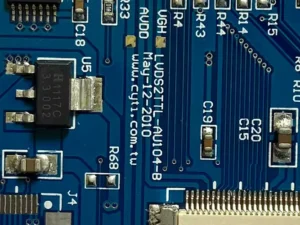
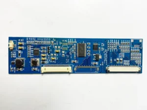
For this product, the copper busbar can be punched first, followed by contour stamping. The finished product after stamping is shown in Figure 3.

Test Analysis of PCB Copper-Embedded Boards
After completing the aforementioned processes for copper-embedded PCB products, the finished boards undergo testing to verify compliance with performance specifications.
-
Test Items
(1) Strength of buried copper busbar PCB grounding copper ring assembly (M4 bolt with copper ring and PCB connection structure).
(2) Tensile strength test: Apply uniform vertical loading until failure.
(3) Torque test: Apply uniform clockwise torque until failure.
-
Test Results
Test results are shown in Table 1.

-
Test Analysis
Test results indicate that the bonding strength between the copper busbar and single-sided substrate is high, with tensile strength and torque exceeding design requirements.
This demonstrates that the material thickness and compression bonding process are both feasible and reliable.
Analysis of failure modes indicates that the final fracture occurred at the PCB substrate (non-copper busbar interface), demonstrating that the strength of the embedded copper busbar structure exceeds the substrate’s inherent load-bearing capacity.
Further validation of long-term reliability under dynamic loading is required.
Conclusion
The PCB embedded copper busbar technology presented herein involves directly laminating copper busbars within the PCB, addressing the shortcomings of traditional soldered busbar methods.
Structurally, this technology ensures the copper busbar is tightly bonded to the substrate through lamination, resulting in enhanced stability.
Direct connection between the busbar and the inner layer copper foil of the circuit board improves current carrying capacity.
It also reduces impedance and heat generation, minimizing current loss to better meet thermal dissipation demands in high-power applications.
This approach fundamentally eliminates risks associated with solder damage or oxidation failure.