Aerospace electronic and electrical equipment continuously faces erosion from special environmental factors such as humid heat, mold, salt spray, and corrosive gases during service.
This leads to issues like corrosion and mold growth on PCBA electronic components.
Minor cases may affect appearance, while severe situations can cause electronic product malfunctions and result in complete system failures.
Therefore, to enhance the reliability of electronic and electrical equipment during service, a layer of three-proof material is typically applied to the surface of circuit boards.
This prevents component failures such as pin corrosion and low-pressure arcing under conditions of humidity, heat, mold, and salt spray.
Aviation electronics are high-value, low-volume, and diverse. When their functions fail or performance degrades, immediate replacement is impractical, necessitating repair by specialized technicians.
PCBA assemblies are typically the core components of electronic and electrical products.
The most critical step before repairing such components is the removal of the local or overall three-proof coating.
The quality of this removal and the restoration of the coating directly determine the final repair quality and operational reliability of the product.
Types and Properties of Triple-Proof Coating
Types of Triple-Proof Coating
Triple-proof coatings are typically transparent and uniformly applied to the surface of circuit boards.
They protect various packaged components from corrosion and damage caused by harsh environments, thereby extending the operational lifespan of electronic products and ensuring stable, reliable performance.
Currently, the industry commonly uses five types of three-proof coatings classified by material: epoxy resin (ER type), acrylic resin (AR type), polyurethane resin (VR type), silicone resin (SR type), and xylene (XY type).
In the aerospace sector, acrylic resin, polyurethane resin, and silicone resin are most frequently employed.
Epoxy resin and xylene are less commonly used: the former due to its hard texture and strong adhesion, which complicates removal during maintenance; the latter due to its significant health impact on workers.
Performance of Triple-Proof Coating Layers
The properties of several types of triple-proof materials are described below.
(1) Acrylic Type.
Easy to apply, offering ideal electrical properties, physical properties, and mold resistance.
Features a long pot life, short curing time, and non-exothermic curing that avoids damaging heat-sensitive components.
Exhibits no shrinkage after curing. However, this coating is solvent-sensitive, making it amenable to rework.
(2) Polyurethane Type.
Available in single-component and two-component formulations.
Offers excellent long-term dielectric properties, superior moisture resistance, and chemical resistance.
Replacement of components or repair of circuit boards requires specialized stripping agents.
Prior to coating, circuit boards must be thoroughly cleaned, with particular attention to ensuring no moisture is present.
(3) Epoxy Resin Type.
Typically two-component with a short pot life. Offers excellent moisture resistance, salt spray resistance, and chemical resistance.
Physical removal of the epoxy film is required when replacing components or repairing circuit boards.
Protective measures must be applied to fragile components before coating.
(4) Silicone Resin Type.
Offers excellent thermal performance, capable of continuous operation at 200°C.
Additionally, it provides strong moisture resistance and corrosion resistance.
Suitable for high-frequency circuit boards with high-heat components, such as those containing numerous high-power resistors.
This coating has a short pot life and a relatively high thermal expansion coefficient.
When repairing the circuit board, the silicone film must be removed.
(5) Paraxylene-based.
Poly-paraxylene-based conformal coatings exhibit uniform thickness, dense pinhole-free films, stress-free transparency, additive-free composition, non-damaging properties to substrates, and superior electrical insulation and protection.
They are currently recognized as the most effective protective coating material for high-frequency components, high-density assemblies, and high-insulation modules.
The protective effect requires the coating to achieve a certain thickness.
Based on material properties, the qualified dry film thicknesses after curing for the above types of conformal coatings are shown in Table 1.
| Material Type | Coating Thickness / mm |
|---|---|
| Acrylic Resin | 0.03 ~ 0.13 |
| Epoxy Resin | 0.03 ~ 0.13 |
| Polyurethane Resin | 0.03 ~ 0.13 |
| Silicone Resin | 0.05 ~ 0.21 |
| Parylene Resin | 0.01 ~ 0.05 |
Selective Removal of IPX3 Protective Coatings
The critical process preceding component rework on PCBA assemblies is the removal of IPX3 protective coatings.
This requires either localized or full-board coating removal based on the size of the rework area.
During localized operations, surrounding coatings—specifically the integrity of components—must remain unaffected.
Simultaneously, the IPX3 coating in the designated rework zone must be thoroughly removed to enhance operational efficiency.
Currently, common methods for removing PCB conformal coatings include scraping, peeling, heating, solvent application, and micro-sandblasting.
Based on material types and operational experience, Table 2 outlines the safest and most efficient removal methods for each coating material, along with the time required to remove 25 cm².
| Material Type | Removal Method (Removal Time in Seconds / 25 cm²) |
|---|---|
| Acrylic Resin | Solvent method (600), Micro sandblasting (20) |
| Epoxy Resin | Heating method (300), Scraping method (almost complete), Micro sandblasting (120) |
| Polyurethane Resin | Micro sandblasting (100), Heating method (300) |
| Silicone Resin | Peeling method (120) |
| Poly-xylene Resin (Parylene) | Heating method (120), Micro sandblasting (100) |
As shown in Table 2, except for silicone resin, micro-sandblasting can effectively remove conformal coatings.
Practical production experience indicates that solvent removal, scraping, and peeling methods require longer processing times, while heating methods demonstrate relatively higher efficiency.
Micro-sandblasting achieves the highest efficiency, particularly for acrylic resin coatings.
Based on these findings, this paper focuses on introducing sandblasting as a method for removing conformal coatings from PCBA electronic components.
Micro-Sandblasting Equipment
Micro-sandblasting equipment comes in many brands, such as the Formula 1200 from the UK’s GUYSON Company, Crystal Mark’s TURBO-MAX CCR from the USA, and PAS M1 from France’s Quantel, alongside several domestic models.
Their operating principle is identical: using sandblasting to press specially formulated abrasive particles into a compressed air stream, which is then projected onto the surface of circuit boards requiring three-proof coating removal.
These systems typically incorporate anti-static nozzles and particle balance generators to neutralize electrostatic charges generated during high-speed particle movement.
ESD voltage is controlled within ±10V, and circuit boards can be grounded within the work chamber to dissipate static electricity.
Adjusting the diameter of the abrasive particles enhances removal efficiency for different coatings: larger particles are suitable for epoxy and polyurethane, while smaller particles are preferred for acrylic coatings.
Removal Operations and Inspection
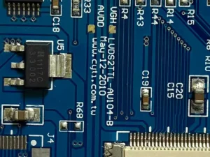
When performing localized work, use protective tape to cordon off the work area (see Figure 1).

Then set the air pressure of the micro-sandblasting equipment according to the type of three-proof material: typically 60 psi for acrylic, and 80 to 90 psi for epoxy and polyurethane.
During operation, maintain a 2–5 cm distance between the abrasive nozzle and the PCB surface.
Hold the nozzle at a 45°–60° angle to the board surface. Progressively remove the conformal coating across the work area by observing the nozzle’s path.
If the material contains fluorescent components, activate the equipment’s UV lamp for enhanced visibility.
If substrate damage is observed during operation, promptly reduce the equipment air pressure.
Since removing solder mask from solder joints is more challenging than from the board surface, extend the removal time as needed.
Upon completion, all applied solder masks must be fully removed without damaging the PCB surface.
Selective Coating of Three-Proof Protective Coatings
For circuit boards requiring localized or full-board three-proof coating after repair, perform peripheral area protection as shown in Figure 1 during localized spraying operations.
Coating restoration can be achieved through manual brushing or the use of selective spraying equipment.
To enhance coating uniformity and control three-proof thickness, selective coating equipment is typically employed.
When using equipment for selective coating, parameters such as spray pressure, atomization pressure, spray height, spray speed, and spray interval must be set.
The equipment’s inherent performance determines these settings and are highly correlated with the atomization valve.
The equipment used in this study is the I-COAT5 selective coating machine, with path settings typically configured as shown in Figure 2.

The test coating material was polyurethane.
The equipment was configured with an atomization pressure of 0.2 MPa, an atomization valve height of 2 cm, a path spacing of 10 mm, and an atomization valve travel speed of 100 mm/s.
The cured thickness was approximately 70 μm. The atomization valve travel speed was 200 mm/s, yielding a cured thickness of approximately 50 μm.
The post-curing dry film thickness met the requirements specified in Table 1, thereby satisfying IPC-610 standards.
For components such as QFJ, BGA, and vertically mounted devices, tilt the atomization valve nozzle to enhance coverage of the conformal coating layer and achieve effective protection.
Additionally, the cured conformal coating layer must not exhibit defects such as peeling, orange peel, bubbles, or cracks.
Conclusion
The conformal coating applied to the surface of PCBA electronic components effectively protects circuit boards from corrosion and damage caused by harsh environments such as moisture, mold, and salt spray.
This enhances and extends their service life while ensuring operational safety and reliability.
In the rework and repair of aerospace electronics, thoroughly removing the conformal coating from the surface of the circuit board under repair is critical.
Achieving high-quality restoration of the conformal coating post-repair is also a key aspect of the rework process.
With the adoption of new conformal coating materials, increased integration of electronic components, and reduced anti-static capabilities of highly integrated chips, practitioners must continuously optimize and enhance conformal coating removal techniques in electronics rework.
This involves researching new methods, improving operational efficiency, and ensuring work quality.