
In recent years, with continuous breakthroughs in artificial intelligence, the electronic information industry has entered a phase of rapid development.
Electronic products are constantly evolving toward higher density, miniaturization, and higher performance, placing greater demands on the structural complexity and manufacturing precision of printed circuit boards (PCBs).
As one of the most critical processes in PCB manufacturing, the machining quality of mechanical drilling directly affects the reliability and electrical performance of through-holes.
During micro-drilling, the cutting behavior between the drill bit, the copper foil, and the substrate is extremely complex, with the cutting and chip removal mechanisms of the copper foil layer being particularly critical.
The formation, morphology, and evacuation behavior of copper foil chips not only affect hole wall integrity and burr formation but also directly relate to drill bit wear, chip evacuation capacity, and overall machining stability.
They are also critical factors in determining drilling quality, tool life, and the performance of subsequent electronic component assembly.
In-depth research on the formation and evolution of copper foil chips in PCB mechanical drilling is of great significance.
This research possesses important theoretical value and engineering practicality.
It contributes to the optimization of machining process parameters and the improvement of machining efficiency.
It also helps enhance PCB drilling quality and extend micro-drill service life.
Currently, research on chip behavior during mechanical PCB drilling has made some progress.
Inspection and observation methods have continuously evolved in drilling research.
Researchers have gradually upgraded traditional visual observation and cross-sectional inspection techniques.
Modern approaches integrate high-speed photography and numerical simulation to form comprehensive analytical methods.
These advanced methods enable researchers to accurately capture dynamic variations in chip morphology.
They also provide a critical foundation for in-depth exploration of chip formation principles and influencing mechanisms in drilling processes.
Regarding chip control, existing research has further explored this issue from two dimensions: process optimization and structural design.
Current relevant studies focus on multiple effective improvement strategies.
Common approaches include optimizing the geometric parameters of chip-breaking grooves, fabricating microstructures on tool surfaces, and adopting ultrasonic vibration-assisted machining.
These methods mainly aim to improve the stability of chip-breaking and chip evacuation processes.
Chips generated by micro-pit-textured cemented carbide tools exhibit a flatter bottom surface.
Such chips present significantly enhanced curvature and coiling degrees.
These morphological features make the produced chips more susceptible to fracture.
Existing research has achieved phased progress in areas such as chip morphology evolution, chip evacuation mechanisms, and numerical simulation analysis.
However, PCBs are typical multi-component, multi-layer heterogeneous composite materials;
The heterogeneity of their material composition and the complexity of their interlayer structure result in distinctly unique chip formation behavior, making it difficult for current studies to elucidate the subtle differences in chip behavior characteristics.
This paper performs a quantitative characterization analysis on regularly shaped and morphologically stable copper foil chips.
It establishes quantitative correlations between copper foil chip characteristics and mechanical drilling parameters.
The analysis also covers the structural parameters of micro-drills. This study aims to realize precise control of the chip formation process.
It further provides theoretical support for the optimization of the overall drilling process.
This study provides theoretical support and engineering guidance for improving hole wall quality, extending micro-drill life, and enhancing machining stability during the micro-drilling of PCBs.
Experimental Equipment and Protocol
Experimental Equipment and Workpiece Specifications
This experiment utilized a Hitachi ND-6Y220E high-speed drilling machine (300,000 rpm) to conduct drilling experiments.
We collected and characterized the copper foil chips generated during drilling and used a Keyence VHX-5000 ultra-deep-field microscope to capture the morphology, dimensions, and microscopic cross-sectional features of the chips.
We use a FASTCAM Mini UX100 high-speed camera equipped with a Nikon macro lens to record and analyze the dynamic chip removal process in real time.
The frame rate was set to 32 kfps, and the exposure time was set to 1.83875 s.
This drilling test adopts a 2.7 mm-thick IT180A board processed via the single-sheet lamination method.
This multilayer PCB contained 14 layers of copper foil, of which the two outer layers had a thickness of 20 µm, and the inner layers had a thickness of 32 µm.
The experimental machining parameters are shown in Table 1.
This machining process adopts an MLE1070-coated aluminum cover plate and a 1.5 mm-thick phenolic backing plate, with the cover plate removed during chip observation and collection.
The number of drill holes was set according to experimental requirements, with the aim of investigating the patterns of change in chip behavior at different stages of the machining process.
| No. | Spindle Speed (kr·min⁻¹) | Feed Rate (mm·s⁻¹) | Retract Speed (mm·s⁻¹) | Chip Load (μm·rev⁻¹) |
|---|---|---|---|---|
| 1 | — | 20 | — | 6.32 |
| 2 | 190 | 45 | — | 14.21 |
| 3 | — | 70 | 300 | 22.11 |
| 4 | 110 | — | 300 | 21.82 |
| 5 | 190 | 40 | — | 12.63 |
| 6 | 270 | — | — | 8.89 |
Table 1. Drilling Parameters
Test Bit Selection and Controlled-variable Experimental Design
This study selected a USF-type drill bit with a diameter of 0.20 mm as the basic research subject.
This drill bit features a double-edge, single-flute design, with a gradual structural transition in the middle of the shank that allows for a configuration shift from double flutes to a single flute.
Within this basic drill bit design framework, we adopt the controlled variables method to systematically adjust and comparatively test the drill bit’s key structural parameters.
The structural adjustment plans and variable settings for the drill bit are shown in Table 2.
| Structural Parameter | Parameter Value |
|---|---|
| Unchanged | Helix angle: 50°; Point angle: 130° |
| Helix Angle (°) | 40, 45, 50, 55 |
| Point Angle (°) | 120, 130, 165 |
Table 2. Adjustment Scheme for Micro-Drill Structural Parameters Used in the Experiment
Chip Sample Quantitative Measurement and Error Control Method
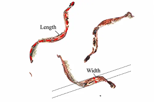
We quantitatively analyze the geometric characteristics of the collected chip samples and manually measure the length and width of the chips via microscopic images (see Figure 1).
Orientation deviations may appear during chip imaging. Manual measurement is also likely to introduce subjective errors.
For this reason, no less than 25 chip samples were chosen for measurement.
Samples were fabricated corresponding to each group of machining parameters and drill geometries.
The mean and maximum dimensional values of all measured chip samples were calculated accordingly.
These quantitative indices were adopted to evaluate the chip size characteristics under corresponding machining conditions.
Analysis and Discussion
Chip Morphological Characteristics
We performed a continuous drilling test of 100 holes with the cover plate removed and the drill’s dust extraction function disabled.
We collected the resulting chips for subsequent observation and analysis.
The test results indicate that the chips generated during drilling consisted primarily of large copper foil chips.
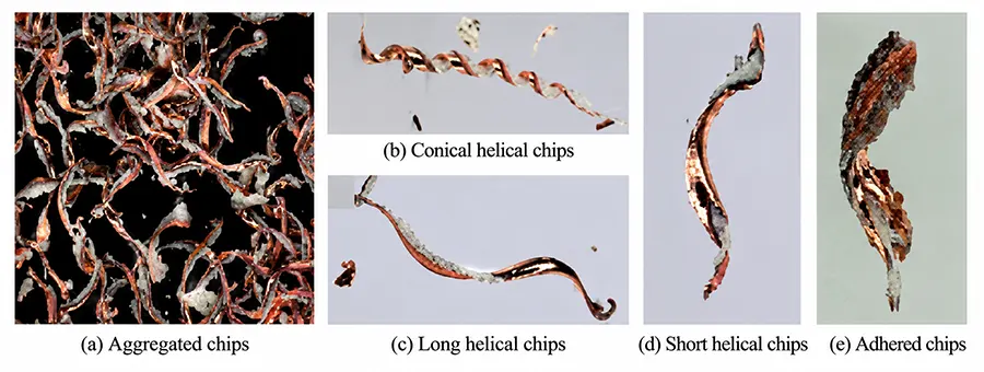
These chips generally appeared agglomerated, with resin components adhering to their surfaces, as shown in Figure 2 (a).
After separation, the copper foil chips can be classified into four categories: long conical spiral chips, long spiral chips, short spiral chips, and agglomerated chips.
The morphologies of each chip type are shown in Figures 2(b) through (e), respectively.
Further analysis of the morphology revealed that copper foil chips generally exhibit the characteristic of being “smooth on one side and rough on the other.”
Among these, the smooth surface of the long conical spiral chips is the newly formed machined surface created during the drilling process;
The smooth surfaces of other chip types are primarily formed by friction between the spiral surface and the workpiece bore wall.
Long conical spiral chips are produced in relatively small quantities; they have a small diameter but a shorter pitch, and this type of chip typically forms during the initial penetration stage of drilling.
During this stage, the drilling process is not constrained by the bore wall, making it easy for the chip axis to deviate from the drill bit axis.
In addition, agglomerated chips are caused by excessively high temperatures in the chip formation zone during drilling;
Under high temperatures, the resin bonds multiple individual chips together, ultimately resulting in a significant increase in the overall size of the chip.
The Effect of Spindle Speed and Feed Rate on Chip Formation
1. Variation Law of Chip Geometric Dimensions Under Different Process Parameters
Spindle speed and feed rate are the most critical process parameters in PCB drilling.
Properly setting and optimizing these two parameters plays a vital role in improving the machining accuracy of hole walls, suppressing burr formation, and extending tool life.
In this section, based on the drilling process parameters listed in Table 1, we analyze the specific patterns of how variations in spindle speed and feed rate affect the morphology of PCB chips and chip evacuation behavior.
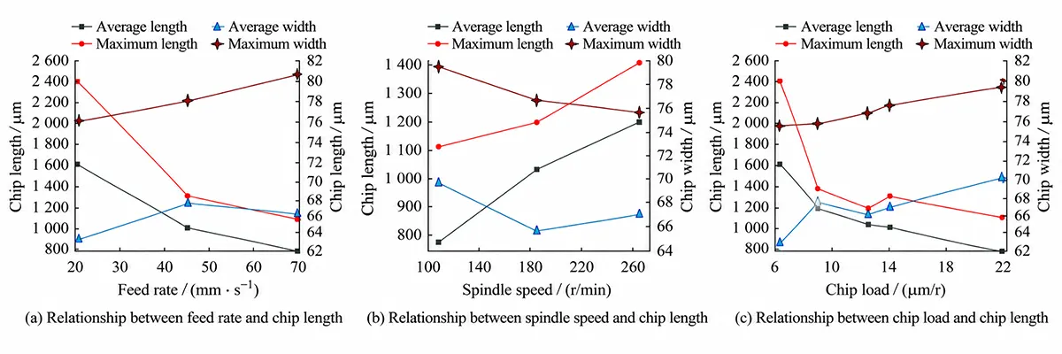
Figure 3 shows the statistical results of chip dimensions obtained after drilling 100 holes with a standard drill bit under different machining conditions.
As shown in Figure 3(a), at a constant spindle speed, chip length tends to decrease as the feed rate increases, while chip width tends to increase as the feed rate increases.
As shown in Figure 3(b), under constant feed rate conditions, chip length increases as spindle speed increases, while chip width decreases as spindle speed increases.
The formula for calculating the cutting load is as follows:

In the equation: Cload is the cutting load, in µm/r; F is the feed rate, in mm/s; S is the spindle speed, in kr·min−1.
Using Equation (1), the spindle speed and feed rate are converted to cutting load.
As shown in Figure 3(c), the variation patterns of chip length and width with cutting load are consistent with their variation patterns with feed rate.
The chip evacuation space along the spiral flutes is unrestricted during drilling.
In contrast, the circumferential evacuation space is constrained by the drill diameter.
This difference leads to a wider variation range in chip length. Meanwhile, the variation range of chip width remains relatively narrow.
2. Surface Characteristics of Chips Under Different Cutting Loads
Chips present distinct evolutionary patterns in surface topography, color variation, resin adhesion, and entanglement tendency under different cutting loads.
Under high-load cutting conditions, chip dimensions exceed the accommodation capacity of drill chip flutes.
The friction between chips, hole walls, and chip flute walls increases significantly.
The mutual squeezing force among adjacent chips also rises remarkably.
These coupled effects raise the temperature of the cutting zone. Eventually, severe plastic deformation occurs on the chips.
3. Chip Wrapping Mechanism Observed From High-speed Imaging
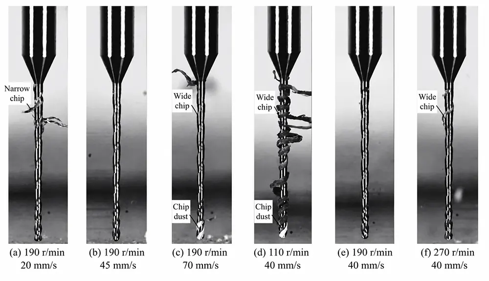
The chip withdrawal process recorded by a high-speed camera is shown in Figure 4.
As can be seen from Figure 4, whether the cutting load is too high or too low, it increases the probability of chip wrapping.
When the cutting load is high, the chip width increases, and the helical chip flutes cannot effectively accommodate and evacuate the chips, which easily leads to blockage at the leading edge of the chips.
This, in turn, causes the chips to wrap around the drill body to a significant extent, as shown in Figure 4 (c) and (d);
When the cutting load is low, although the chip width is smaller, the chip length is longer, making it easier for the chip to wrap around the drill body along the direction of the helical flutes, as shown in Figure 4 (a) and (f).
The Effect of the Number of Holes Drilled on Chip Characteristics
1. Experimental Scheme for Studying Chip Evolution with Cumulative Drilled Holes
To investigate the evolution of chip morphology as a function of the number of holes drilled, this study used a reference drill bit to drill a cumulative total of 2,000 holes under standard operating conditions.
Specifically, after every 500 holes were drilled, the drill bit was removed and used to drill an additional 100 holes without a cover plate to collect chips.
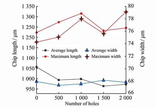
The variation law is illustrated in Figure 5. With the growth in the number of drilled holes, the maximum chip length fluctuates between 1200 μm and 1300 μm.
The average chip length presents a gradual downward trend. It decreases from 1050 μm to roughly 950 μm.
By contrast, the maximum chip width shows an upward tendency, rising from 74 μm to about 80 μm.
The average width stays basically stable and remains around 68 μm.
2. Morphological Differences Between Long and Short Chips at Different Drilling Stages
Judging by the chip morphology, as the number of drill holes increases (100 holes—500 holes—1,000 holes—1,500 holes—2,000 holes), the number of short chips gradually increases; these short chips tend to stick together due to the resin.
For chips from the same batch, obvious differences exist between long chips and short chips.
Long chips have relatively intact surfaces with little resin adhesion. In comparison, short chips show wrinkled surfaces and carry more adhered resin.
3. Correlation Between Tool Wear and Chip Formation Mechanism Transition
Further analysis of the drill bit’s wear revealed that after drilling 2,000 holes, the cross-edge had widened and the main cutting edge had become dull.
It can therefore be concluded that the generation of short chips is caused by a decline in cutting performance resulting from drill bit wear. Initially, the main cutting edge was intact, and the cutting conditions were normal;
With the increase in the number of drilled holes, the main cutting edge of the micro-drill gradually suffers wear.
The overall cutting performance of the tool accordingly deteriorates.
The material removal mechanism gradually transforms from cutting-dominated to extrusion-dominated material removal.
This transition generates a greater number of short chips. The produced chips feature smaller sizes and more severe plastic deformation.
The Effect of Helix Angle and Point Angle on Chip Formation
1. Fundamental Influence Mechanism of Drill Geometric Features
The helix angle of a drill bit is defined as the angle between the tangent to the line where the helix groove intersects the outer cylindrical surface of the drill bit and the drill bit’s axis.
It has a significant impact on the tool’s sharpness, rigidity, and chip evacuation space.
Among these, the helix angle in the cutting edge region is the key factor determining the tool’s cutting sharpness, while the helix angle in the section behind the cutting edge primarily regulates the tool’s chip evacuation capability.
For double-edged, single-flute microdrills, the chip evacuation space is most sensitive to changes in the helix angle of the spiral flutes.
The helix angle changes the chip flow direction and the cross-sectional area of chip evacuation channels.
It directly affects the curling characteristics, continuity, and fracture mode of generated chips.
These variations ultimately lead to distinct differences in chip macroscopic morphology.
Additionally, the rake angle of a microdrill also influences the chip formation process and chip evacuation efficiency.
Variations in rake angles change the contact state between the cutting edge and workpiece material.
Such alterations adjust the distribution of cutting forces and the deformation behaviors of the cutting layer.
Ultimately, the chip evacuation efficiency is effectively regulated.
Variations in the drill point angle alter the extrusion and shear paths of materials during the initial cutting deformation stage.
Such differences lead to diverse bending tendencies and fracture behaviors of chips at the early formation stage.
These varying characteristics ultimately induce discrepancies in the macroscopic chip morphology.
Therefore, based on the geometric parameters listed in Table 2, this section will analyze the specific effects of changes in the helix angle and point angle on the morphology and chip evacuation behavior of PCB chips.
2. Effect of Helix Angle on Chip Size, Evacuation Space and Chip Status
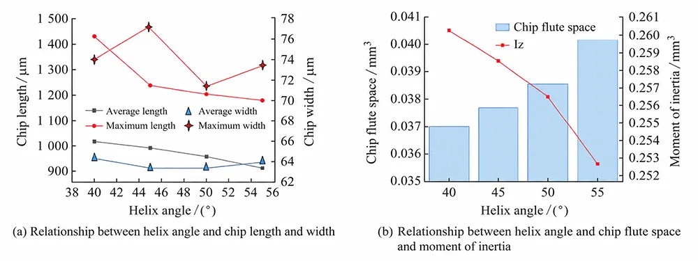
As illustrated in Figure 6(a), comparisons of chip size characteristics are performed under different helix angles.
The comparison results show that chip length tends to decrease with the increase of helix angle.
In the meantime, chip width basically stays constant as the helix angle rises.
As presented in Figure 6(b), this paper calculates the chip evacuation space and axial moment of inertia for drill bits with four different helix angles.
The calculation results show that the chip evacuation space increases with the rising helix angle.
In contrast, the axial moment of inertia decreases as the helix angle increases.
In summary, the core mechanism of increasing the helix angle is to sacrifice a certain degree of drill bit rigidity in exchange for a larger chip evacuation space.
Based on the above analysis, the following conclusions can be drawn. A larger helix angle can significantly expand the chip evacuation space.
Nevertheless, it also prolongs the chip evacuation path along the flutes.
This condition increases the possibility of contact and impact between chips and the bore or flute walls during the evacuation process.
Due to the intensified friction, chips are more prone to fracture or plastic deformation, which manifests macroscopically as a reduction in chip length.
Regarding chip width, the structural region corresponding to the helix angle primarily serves as a chip evacuation channel and does not directly participate in the chip formation process.
Therefore, although the helix angle changes, its effect on chip width is extremely negligible;
This conclusion is consistent with the observational results from this experiment, which showed that chip width remained essentially stable.
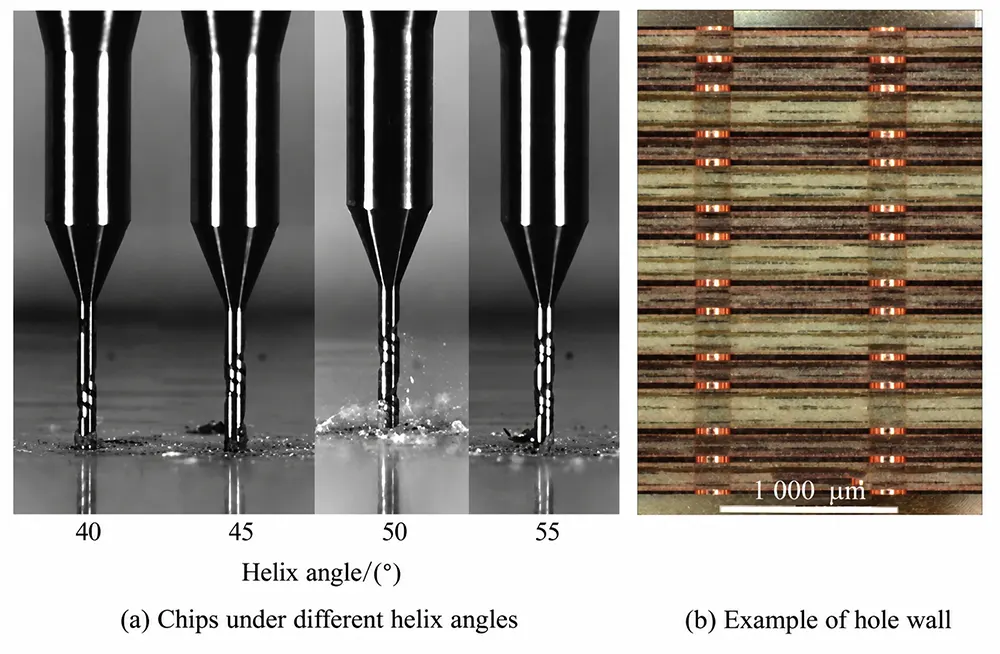
As shown in Figure 7, high-speed photography and cross-sectional analysis reveal that when the helix angle is small, the chips are in a soft state.
This is likely due to insufficient chip evacuation space, causing the chips to undergo significant compression and friction within the hole, resulting in severe deformation, making them prone to fracture and leaving residues on the hole wall.
In contrast, when the helix angle is large, the chips possess higher rigidity.
They can be smoothly discharged along the spiral flutes. This realizes efficient chip evacuation. It also keeps the hole walls relatively clean.
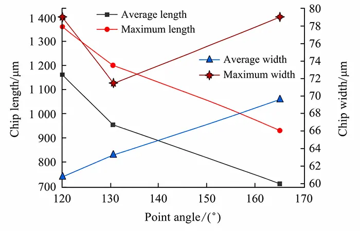
The dimensions of copper foil chips at different rake angles are shown in Figure 8.
Analysis reveals that chip length decreases as the rake angle increases, with the average length dropping from approximately 1,200 µm to about 700 µm—a 40% reduction, which is a very significant change;
The average width of the chips increases slightly as the rake angle increases.
3. Effect of Rake Angle on Copper Foil Chip Dimensions and Cutting Engagement
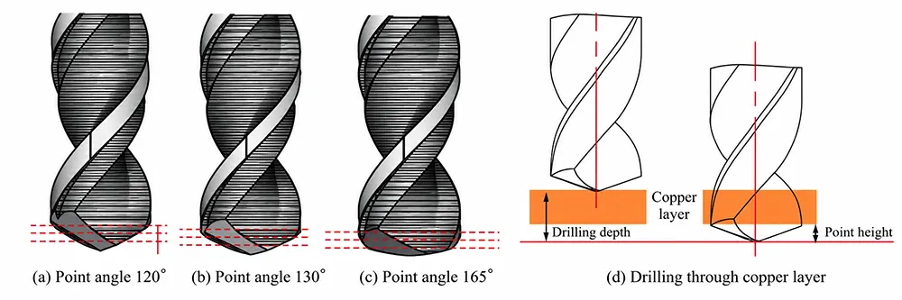
As shown in Figure 9, as the rake angle increases, the height of the outer edge of the microdrill’s main cutting edge gradually decreases.
It can be observed from Figure 9(d). Under fixed cutting parameters, a drill with a larger rake angle needs a shorter penetration stroke for copper foil with identical thickness.
This means fewer rotational revolutions are required for drilling. As a result, the generated chip length becomes correspondingly shorter.
On the other hand, under identical cutting conditions and copper foil thickness, a micro-drill with a larger rake angle possesses a longer cutting edge engagement segment.
This extended active cutting participation further produces chips with a wider width.
Conclusion
This paper investigates the effects of various drilling parameters and micro-drill geometries on chip size, morphology, and chip evacuation.
Through quantitative chip analysis, correlations were established between spindle speed, feed rate, number of drill holes, helix angle, and point angle and chip characteristics.
The main conclusions are as follows:
(1) With the rise of chip load, chip length shows a decreasing trend. Meanwhile, the chip width increases correspondingly.
In addition, chip load should be controlled within a reasonable range. Excessively high or low chip load may readily cause chip jamming or thread entanglement.
(2) As the number of holes increases, the cutting edge of the microdrill gradually shifts toward an extrusion-type cutting mechanism, resulting in reduced cutting capacity.
The chips undergo significant deformation and take on a fine, fragmented form, and their length also decreases accordingly.
(3) Increasing the helix angle expands the chip evacuation space and improves chip evacuation conditions, but it also reduces the micro-drill’s rigidity to some extent.
(4) Increasing the point angle significantly shortens the chip length while slightly increasing the chip width.

