In recent years, rigid-flex boards have been widely used in fields such as medical devices, aerospace, and automotive manufacturing due to their superior performance.
However, because they are difficult to manufacture and costly, they are not cost-effective in applications where the bending requirements are not particularly high.
To address this issue, semi-flexible rigid-flex boards have gradually garnered attention.
Semi-flexible rigid-flex boards combine flexibility and rigidity to a certain extent, capable of meeting the requirements of simple bending applications.
However, existing manufacturing technologies for these boards suffer from issues such as long production cycles and low precision.
This paper will conduct an in-depth analysis of the shortcomings in the manufacturing process of semi-flexible rigid-flex boards to provide efficient and economically viable solutions for optimizing and improving the manufacturing process.
The goal is to promote the widespread adoption and application of these products in actual production while offering valuable insights for technological advancement in related fields.
Overview of Traditional Manufacturing Processes for Semi-Flexible Rigid Board Composite Products
The traditional manufacturing methods for semi-flexible laminated products are as follows.
Depth-controlled Milling Method
Using rigid multilayer board processing technology, operators laminate the rigid boards and then employ a milling cutter to thin the semi-flexible areas, thereby creating the desired semi-flexible regions.
Milling the semi-flexible regions is a time-consuming process that generates a significant amount
of chips and dust; prolonged milling causes wear on the milling cutter, resulting in uneven thickness in the semi-flexible regions and affecting the overall quality of the circuit board.
Window-cutting Method
After operators finish the inner layer patterns, they cut windows in the rigid board material and semi‑cured prepreg (PP) at the positions corresponding to the semi‑flexible regions.
After lamination, the process exposes the semi‑flexible regions.
During the lamination process, under the influence of pressure differentials, the prepreg flows from the rigid region toward the semi-flexible region, causing excessive resin overflow that affects the product’s appearance and flexural performance.
Operators typically enlarge the size of the prepreg cutouts to prevent excessive resin overflow.
However, this can lead to voids caused by resin flow, which in turn affects the product’s reliability.
Solution and Manufacturing Process
Solution
We propose an innovative method for manufacturing semi-flexible/rigid laminate products—the controlled-depth windowing method—with the following process:
First, operators laminate the semi-flexible substrate and PP together in a single press.
Next, they cut a window into another PP sheet at the position matching the semi-flexible area.
Then, they mill a groove into the rigid board at the corresponding location.
Finally, they laminate all sheets a second time.
After they finish lamination, they remove material from the regions above the semi-flexible areas with a milling cutter, following the milled groove dimensions to expose the semi-flexible areas.
By combining the core technical advantages of the controlled-depth milling method and the window-cutting method, this approach effectively addresses the shortcomings of these two traditional fabrication methods.
The process flowchart for the controlled-depth window-cutting method is shown in Figure 1.
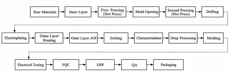
In the process flow shown in Figure 1, final quality control (FQC) is the final inspection step, primarily involving a comprehensive inspection of the circuit boards in accordance with customer requirements and industry standards;
Prganic solderability preservative, OSP) oxidation resistance is one of several surface treatment methods for printed circuit boards;
The primary function of the quality assurance (QA) process is to ensure the overall quality of the printed circuit boards.
Key Process Steps
This product is a 6-layer board with a thickness of (1.60 ± 0.16) mm. Researchers describe the key process steps in the above workflow in detail below.
1. Cutting
Cut the inner layer substrates, PP, and copper foil for semi-rigid and rigid boards.
The substrates undergo a pre-baking treatment to reduce the board’s coefficient of thermal expansion.
2. First Lamination
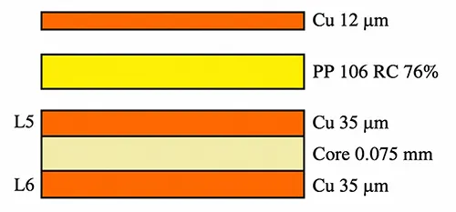
Engineers designate the top and bottom surfaces of the semi‑flexible board as layers L5 and L6, respectively.
On layer L5, a sheet of PP is first laid to protect the circuit patterns in the semi-flexible area;
Next, a copper foil is laid in the reverse orientation, ensuring its smooth side contacts the PP.
Laying the copper foil in this manner ensures that the PP on Layer L5 remains undamaged during subsequent lamination;
After lamination, operators must etch away the copper foil on Layer L5. Figure 2 shows the stack‑up structure for the first lamination.
3. Milling Grooves and Cutting Windows
After operators complete lamination, they must mill grooves into the rigid board.
These grooves match the dimensions of the semi-flexible region; Figure 3 shows the geometry.
When operators mill the grooves, they control the cutting depth according to the rigid board thickness.
Next, windows are cut into the PP by milling openings that align with the positions of the grooves on the rigid board.
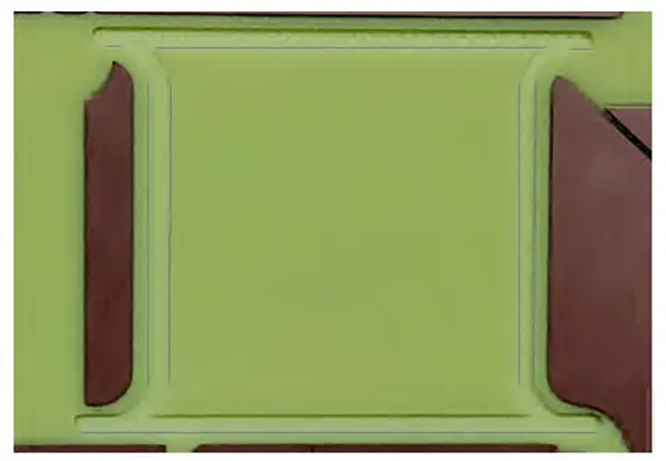
Analysis of Key Points for Milling Grooves and Cutting Windows: The size of the window opening affects the overall quality of a semi-flexible rigid-flex board.
If operators size the window opening identically to the milled groove on the rigid panel, the rigid panel squeezes the PP during lamination.
This forces the PP to overflow into the semi-flexible area and creates adhesive overflow.
This overflow not only affects the appearance of the semi-flexible area but also compromises its flexural performance.
Operators typically enlarge the PP window opening to prevent excessive adhesive overflow.
However, if they make the PP window too large, it may form adhesive voids, which cause panel rupture and delamination.
Therefore, operators must control the enlarged PP window size and reserve a region for adhesive overflow.
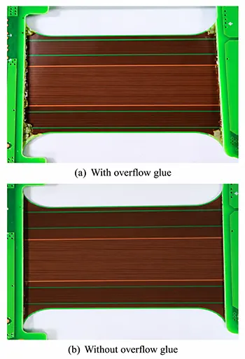
Researchers ultimately determined that enlarging the PP window opening by 200 μm yields the optimal design, as Figure 4 illustrates.
Figure 4 (a) shows a product with a PP opening size identical to that of the rigid board, while Figure 4 (b) shows a product with a PP opening size enlarged by 200 μm.
It is clearly evident that the semi-flexible region of the product in Figure 4 (a) exhibits resin overflow, whereas the product in Figure 4 (b) shows no such overflow.
4. Second Lamination
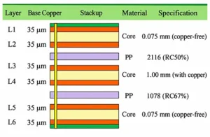
The second lamination involves the overall lamination of the structure contained within the semi-flexible rigid-flex board; the specific stack-up structure is shown in Figure 5.
5. Solder Mask Application
Rigid-board solder mask ink lacks flexibility, so operators select flexible-board ink to print the semi-flexible regions.
This choice improves the flexibility of these regions and boosts the overall flexural performance of the semi-rigid-flex board.
6. Depth-controlled Milling
In the aforementioned slot milling and window cutting process, engineers design slots on Layer L4 of the rigid board and windows on the PP layer.
During depth-controlled milling, operators machine according to the dimensions of the slots on Layer L4.
As they mill from Layer L1 to Layer L4, they fully machine through the slots on Layer L4.
Key Points of Depth-Controlled Milling: In conventional milling operations, an unevenly positioned board or errors in the milling cutter’s depth of cut can damage the circuits in the semi-flexible region.
Therefore, to ensure the integrity of the circuits in the semi-flexible region, a milling groove is designed on Layer L4 of the rigid board.
During actual processing, this ensures that when the milling cutter reaches Layer L4, the cutter head does not extend beyond this milled groove, thereby effectively protecting the circuits in the semi-flexible region of Layer L5.
After operators remove the milled waste material, they complete the remaining processes to fabricate the target semi-flexible rigid-flex board.
Bending Test for Semi-Flexible Rigid-Flex Boards
After manufacturers fabricate the product, operators must test the semi‑flexible region to verify its bending performance.
This test report aims to evaluate the bending performance of semi-flexible rigid-flex boards and observe the impact of bending on the circuit, in order to ensure the reliability and stability of the semi-flexible region in actual applications.
Specimen Preparation
Select a semi-flexible rigid-flexible composite plate as the specimen, ensuring that it is free of defects and damage.
Bending Test: Bend the specimen to the specified bending angle, observe the changes in the specimen during the bending process, and record the relationship between the bending angle and the changes in the specimen.
The permissible bending angles are shown in Figure 6.
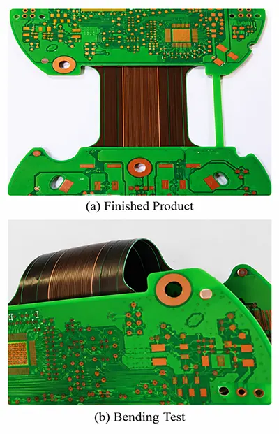
Circuit Inspection: After the bend test, inspect the circuits on the test specimen to check for any breaks, detachments, or other defects.
Test Results
At the specified bending angle, the semi-flexible rigid-flex board demonstrated good bending performance, with no visible cracks or damage observed during the bending process.
After the bending test, no breaks or detachments were found in the circuits on the test specimens, and electrical testing showed that the bending had no adverse effect on signal transmission; the circuits remained intact overall.
Analysis of Test Results
Based on the test results, it is evident that the semi-flexible rigid-flex board possesses a certain degree of bend resistance.
Researchers observed no circuit defects on this semi-flexible rigid-flex product during the bending test.
This characteristic provides a solid foundation for the assembly of electronic components and circuit design.
Conclusion
Based on the test results, the manufacturing process for semi-flexible rigid-flex boards proposed in this paper demonstrates significant advantages over traditional methods.
First, the manufacturing process takes less time, effectively reducing the overall production cycle and improving production efficiency.
Second, the new process allows for more precise dimensional control, which means the products can achieve higher accuracy and consistency, ensuring their reliability and service life.
At the same time, engineers achieve the benefits of this high-precision machining without extra equipment, further demonstrating the cost-effectiveness and efficiency of the new process.
Finally, in terms of appearance, resolving the issue of excess adhesive has improved the product’s aesthetics.
Additionally, the new process delivers outstanding results in both the product’s overall visual appeal and attention to detail.
These aesthetic enhancements not only boost the product’s market appeal but also provide customers with a superior user experience.
In summary, this new manufacturing process for semi-flexible rigid-flex boards surpasses traditional methods, enhancing both product reliability and aesthetic quality, and provides valuable insights for the future development of semi-flexible rigid-flex board manufacturing processes.