Flexible printed circuits (FPCs), with their lightweight and flexible characteristics, are widely used in foldable smartphones, laptop hinges, automotive electronics, and other applications.
The core value of FPCs lies in their “flexibility”—their bend life directly determines the reliability of the product under real-world conditions.
If an FPC rated for 100,000 bends experiences circuit failure after only 30,000 bends in actual use, the entire product faces a risk of failure.
This article explains the standard methods, key parameters, equipment requirements, and practical considerations for flex life testing.
Bend Life Testing: The Core Validation of FPC Reliability
Bend life testing is a test method for FPC specimens. The specimen is repeatedly bent under a specified bend radius, angle, and frequency.
The electrical continuity of the circuit is monitored in real time during testing.
The test continues until specimen failure or completion of preset bending cycles.
It measures not whether an FPC “can be bent,” but rather “how many times it can be bent without failing.”
Unlike one-time mechanical tests such as peel strength and tensile strength, bend life testing is a fatigue test.
Copper conductors experience metal fatigue during repeated bending, with microscopic cracks gradually propagating until an open circuit occurs;
Polyimide (PI) substrates may also delaminate or crack under cyclic stress.
The essence of the bend life test is to simulate real-world bending scenarios throughout the product’s lifecycle, thereby identifying fatigue failure risks in advance.
Standard Methods and Key Test Parameters
Within the industry, flex life testing primarily follows IPC-TM-650 2.4.3 (Reciprocating Flex Test), IPC-TM-650 2.4.9.1 (Flex Life Test), IPC-2223, and GB/T 13557-2017.
Bend Radius: The most critical stress parameter, typically 0.5 mm, 1.0 mm, or 2.0 mm;
In demanding applications such as foldable displays, it can be as low as 0.3 mm.
IPC-2223 recommends that the bend radius be no less than 10 times the thickness of the FPC.
The smaller the radius, the greater the strain on the copper conductors, and the shorter the lifespan.
Bending angle: Commonly ±90° and 180° reciprocating bends;
In some scenarios, inward bends within the 0–180° range are used to simulate foldable screen hinges.
The larger the angle, the greater the strain per bend.
Bending frequency: Typically 10–60 cycles per minute; consumer electronics commonly use 10–30 cycles per minute.
Excessively high frequencies can cause the test specimen to overheat, affecting the material’s fatigue behavior and causing the data to deviate from real-world usage scenarios.
Tensile Load: Certain standards such as GB/T 13557 specify applying constant tensile force.
A typical load is 4.9 N applied to one end of the test specimen. This keeps the specimen in close contact with the mandrel during bending.
It prevents slack, which would otherwise cause deviation of the bending radius.
Environmental Conditions: The standard test environment is 23 ± 2°C and 50 ± 5% RH.
The mechanical properties of PI substrates are sensitive to temperature and humidity, and environmental fluctuations can directly affect bend life data.
Test Principles and Failure Criteria
The operating principles of flex life test equipment fall into two categories:
The linear reciprocating method, in which one end of the FPC is fixed while the other end moves back and forth along a linear guide, causing the test specimen to bend repeatedly around a fixed mandrel;
Another test type is the rotational method. Both ends of the FPC are fixed onto concentric disks.
Relative rotation between disks produces unidirectional or bidirectional bending.
The bending follows a heart-shaped trajectory. This method better simulates the real movement of foldable screen hinges.
During testing, a constant current or voltage must be applied to the FPC circuit, and the loop resistance must be monitored in real time using the four-wire method.
Failure criteria are typically defined as: a sudden increase in loop resistance of ≥10% compared to the initial value, or the occurrence of an open circuit (electrical interruption > 10 ms).
Some standards also classify substrate delamination (delamination area > 5%) and visible cracks in the conductors as failure modes.
The number of cycles at the time of specimen failure is recorded as the bending life;
If the specimen has not failed by the predetermined number of cycles, it is deemed to have passed the test.
Electronic Universal Testing Machine: Ensuring Accuracy in Bending Tests
Bending life tests have three distinctive characteristics. They run a large number of cycles, typically from tens of thousands to hundreds of thousands.
Bending frequency and radius must remain consistent during the whole test. Moreover, specimen failure occurs instantaneously.
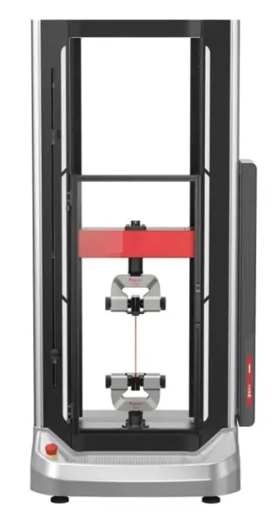
Long-Term Operational Stability for High-Cycle Bending Tests
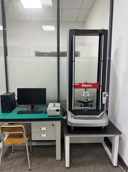
Long-term operational stability is the foundation of bend life testing. The BOYI 2025 series has a Mean Time Between Failures (MTBF) of ≥3,500 hours, with models rated at 5 kN or less featuring a coaxiality of ≤Ø1.5 mm/500 mm.
It can withstand tens of thousands to hundreds of thousands of continuous bending cycles without any performance drift, ensuring that the bending conditions for the first 10,000 cycles are identical to those for the 100,000th cycle.
Precision Control of Bending Motion Parameters
Stable control of bending parameters determines whether stress levels remain constant.
The crossbeam position detection accuracy is within ±0.1% of the displayed value or 10 µm (whichever is greater), with a displacement resolution of 0.01 µm, enabling precise control of the stroke and reciprocating position for each bend;
The crosshead speed accuracy is within ±0.1% of the displayed value, with a speed range of 0.001–1,000 mm/min that can be set continuously.
This ensures stable coverage of the low-speed reciprocating motion required for bending tests, preventing fatigue data distortion caused by frequency fluctuations.
High-Speed Data Acquisition & Automated Test Reporting
Precise capture of the moment of failure relies on a high data acquisition frequency.
Data acquisition frequencies range from 1 kHz (Model 2025) to 5 kHz (Model 2025A), enabling the complete capture of subtle changes in force and displacement during bending cycles.
Combined with the resistance monitoring module, this ensures precise recording of the moment of failure.
In terms of force accuracy, the test force indication error is ≤±0.3% (in the 1/1 to 1/100 range) and ≤±0.5% (in the 1/100 to 1/500 range), enabling precise control of tensile loads.
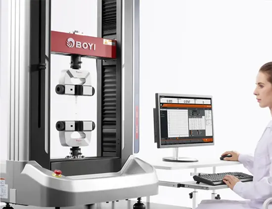
When used with Smartest testing software, users can set the number of cycles and failure thresholds to automatically generate life cycle curves and failure reports.
Details Easily Overlooked in Practice
Specimen preparation must follow standard procedures; the sampling direction should align with the rolling direction of the copper foil or be clearly marked.
The edges must be free of burrs and microcracks, as these can serve as initiation points for fatigue fracture, leading to underestimated service life data.
The bending radius must be measured and calibrated; do not rely solely on the equipment’s nominal values.
Mandrel wear, fixture clearance, and specimen thickness all affect the actual bending radius;
It is recommended to verify these parameters periodically using a feeler gauge or a coordinate measuring machine.
Do not focus solely on the number of bending cycles; pay attention to failure modes as well.
Copper conductor breakage, substrate delamination, and solder joint cracking require entirely different corrective actions; failure analysis is a crucial extension of bending life testing.
Statistical analysis is meaningful only when based on multiple specimens.
Since bend life is a type of fatigue data with high variability, it is recommended to use at least five specimens per group and analyze the results using the median or a Weibull distribution to avoid the randomness associated with a single specimen.
Conclusion
FPC bend life testing is a systematic process: standard methods define the test framework;
Bend radius and frequency determine the stress level;Real-time resistance monitoring captures the moment of failure;
And the displacement accuracy, speed stability, and long-term reliability of the equipment form the foundation for data credibility.
To assess whether a testing solution is reliable, simply ask four questions:
Is the bend radius calibrated based on actual measurements? Does the frequency closely resemble real-world conditions?
Is failure determination based on real-time resistance monitoring? Does the equipment possess sufficient accuracy and stability?
Only when these four questions have clear answers do bend life data truly hold engineering value.