
In the manufacturing of modern electronic devices, printed circuit boards (PCBs) are a critical component.
PCB design involves many factors, among which the properties of PCB materials are one of the key determinants of a PCB’s performance and reliability.
Different PCB materials exhibit varying thermal, mechanical, and electrical behaviors, and the proper selection and application of these materials can optimize PCB performance to the greatest extent.
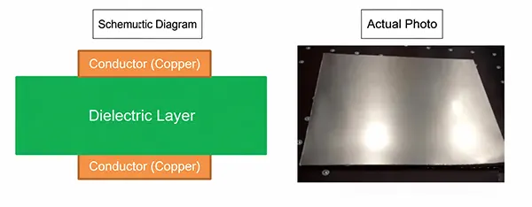
PCBs used in electronic products are generally composed of copper foil and organic materials, as shown in the figure below:
Key PCB Material Properties
Electrical Properties
Electrical properties are one of the key factors determining signal transmission and performance in circuit boards.
Among PCB materials, the dielectric constant is an important electrical property.
The dielectric constant affects signal propagation speed and loss, particularly in high-speed/high-frequency PCB designs.
The dielectric constant varies with frequency, leading to signal dispersion and loss.
When selecting PCB materials, designers should pay particular attention to the frequency dependence of the dielectric constant to ensure accurate signal transmission in high-frequency applications.
Structural Characteristics
The structural characteristics of a PCB affect its mechanical, thermal, and electrical performance.
Two key aspects are the glass weave pattern and the roughness of the copper conductors.
1. Glass Weave Pattern
The glass weave pattern leaves gaps in the PCB substrate, affecting its dielectric constant and mechanical properties.
The gaps in the glass weave pattern cause what is known as the fiber weave effect, leading to variations in the dielectric constant and signal loss.
This is particularly noticeable in high-frequency applications and may affect signal stability and transmission quality.
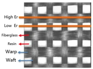
Fig 2
2. Copper Conductor Surface Roughness
The surface roughness of copper conductors affects the impedance of printed circuit boards and signal transmission.
A rougher conductor surface increases losses during high-frequency signal transmission and degrades signal quality.
Designers should select appropriate conductor manufacturing methods and materials to ensure the smoothness of the conductor surface and optimal electrical performance.
Thermal Properties
The thermal properties of PCBs are critical to the heat dissipation and stability of electronic devices.
When selecting PCB materials, thermal conductivity and specific heat capacity are two important factors to consider.
1. Thermal Conductivity and Specific Heat
Thermal conductivity indicates a material’s ability to transfer heat, while specific heat indicates the amount of heat required to change the material’s temperature.
These two parameters jointly influence heat conduction and temperature distribution in circuit boards.
For applications requiring efficient heat dissipation, PCB materials with high thermal conductivity should be selected to ensure that heat is effectively dissipated from the circuit board.
2. Glass Transition Temperature and Coefficient of Thermal Expansion (CTE)
The glass transition temperature and coefficient of thermal expansion (CTE) are key indicators that determine the performance of PCB materials under thermal variations.
The glass transition temperature is the temperature at which a material transitions from a glassy state to a rubbery state, affecting the material’s mechanical properties and stability.
The coefficient of thermal expansion indicates the extent to which a material’s volume changes with temperature, affecting the reliability and stability of the PCB during thermal cycling.
Designers should select PCB materials with appropriate glass transition temperatures and coefficients of thermal expansion to accommodate the expected operating temperature range and thermal cycling environment.
3. Tg Specifications
(1) Sheets with general Tg: 130°C–150°C, such as KB-6164F (140°C) and S1141 (140°C);
(2) Sheets with medium Tg: 150°C–170°C, such as KB-6165F (150°C) and S1141 150 (150°C);
(3) Sheets with high Tg: 170°C and above, such as KB-6167F (170°C) and S1170 (170°C).
FR-4
The term “FR-4” we often refer to is the designation for a flame-retardant material grade. It refers to a material specification requiring that the resin material must be capable of self-extinguishing once ignited. It is not the name of a specific material but rather a material grade. Consequently, there are currently many varieties of FR-4 grade materials used in printed circuit boards, but most are composite materials made from so-called “Tera-Function” epoxy resin combined with fillers and glass fiber.
For example, the FR-4 water-green fiberglass boards and black fiberglass boards we currently manufacture all feature high-temperature resistance, electrical insulation, and flame retardancy.
Therefore, when selecting materials, it is essential to clearly understand the specific characteristics required for your application. This will ensure you select the product that best meets your needs.
Printed circuit board substrates fall into two main categories: organic substrate materials and inorganic substrate materials, with organic substrate materials being the most widely used.
The type of PCB substrate used varies depending on the number of layers; for example, 3- to 4-layer boards require prepreg composite materials, while double-sided boards mostly use glass-epoxy materials.
Latest Information on IEC Standards for PCBs and Related Materials
The International Electrotechnical Commission (IEC) is a global standardization organization composed of national technical committees.
China’s national standards are primarily based on IEC standards, which are among the most rapidly evolving and advanced international standards in the field of PCBs and related substrates.
To help industry professionals understand IEC technical standards for PCBs and related materials, and to accelerate the alignment of printed circuit technology with international standards, the following is a compilation of information on currently valid IEC standards for PCB substrates (laminated boards), PCBs, and related materials, along with the relevant test method standards and their revision status:
Test Method Standards for PCBs and Substrates:
1. IEC 61189-1 (1997-03): Test methods for electronic materials, interconnections, and assemblies—Part 1: General test methods and methodology.
2. IEC 61189 (1997-04): Test methods for electronic materials, interconnections, and assemblies—Part 2: Test methods for interconnection materials. First revision: January 2000
3. IEC 61189-3 (1997-04): Test methods for electronic materials, interconnections, and assemblies—Part 3: Test methods for interconnections (printed circuit boards). First revision: July 1999.
4. IEC 60326-2 (1994-04): Printed circuit boards—Part 2: Test methods. First revision: June 1992.
PCB-Related Material Standards
1. IEC 61249-5-1 (November 1995) Materials for Interconnections—Part 5: Specifications for Uncoated Conductive Foils and Films—Part 1: Copper Foil (for the Manufacture of Copper-Clad Laminates)
2. IEC 61249-5-4 (June 1996) Printed Circuit Boards and Other Interconnection Materials—Part 5: Specifications for Uncoated Conductive Foils and Films—Part 4: Conductive Inks.
3. IEC 61249-7 (April 1995) Interconnection Materials— -Part 7: Specifications for Core Materials—Part 1: Copper/Invar/Copper.
4. IEC 61249-8-7 (1996-04) Materials for Interconnections—Part 8: Specifications for Non-Conductive Films and Coatings—Part 7: Marking Inks.
5. IEC 61249-8-8 (June 1997) Materials for Interconnections—Part 8: Specifications for Non-Conductive Films and Coatings—Part 8: Permanent Polymer Coatings.
Printed Circuit Board Standards
1. IEC 60326-4 (December 1996) Printed Circuit Boards— -Part 4: Internally Connected Rigid Multilayer Printed Circuit Boards—Sub-specifications.
2. IEC 60326-4-1 (1996-12) Printed Circuit Boards—Part 4-1: Internally Connected Rigid Multilayer Printed Circuit Boards—Sub-specifications—Part 1: Detailed Specifications for Capabilities—Performance Levels A, B, C.
3. IEC 60326-3 (May 1991) Printed Circuit Boards—Part 3: Design and Use of Printed Circuit Boards.
4. IEC 60326-4 (January 1980) Printed Circuit Boards—Part 4: Specifications for Single- and Double-Sided General-Purpose Printed Circuit Boards (First revision of this standard in November 1989).
5. IEC 60326-5 (1980-01) Printed Circuit Boards—Part 5: Specifications for Single- and Double-Sided General-Purpose Printed Circuit Boards with Plated-Through Holes (First Revision, [Month] [Day], [Year], 1989).
6. IEC 60326-7 (1981-01) Printed Circuit Boards—Part 7: Specifications for Single- and Double-Sided Flexible Printed Circuit Boards (Without Metallized Holes) (First Revision: November 1989).
7. EC60326-8 (January 1981) Printed Circuit Boards—Part 8: Specifications for Single- and Double-Sided Flexible Printed Circuit Boards with Plated-Through Holes (First revised in November 1989).
8. EC60326-9 (January 1981) Printed Circuit Boards—Part 9: Specifications for Single- and Double-Sided Flexible Printed Circuit Boards (with Plated-Through Holes) (First revised in November 1989).
9. EC60326-9 (1981-03) Printed Circuit Boards—Part 10: Specifications for Rigid-Flex Double-Sided Printed Circuit Boards (with Metallized Holes) (First revised in November 1989).
10. EC60326-11 (March 1991) Printed Circuit Boards—Part 11: Specifications for Rigid-Flex Multilayer Printed Circuit Boards (with Metallized Holes).
11. EC60326-12 (August 1992) Printed Circuit Boards—Part 12: Specifications for Integral Laminated Panels (Semi-finished Multilayer Printed Circuit Boards).
(1) Paper-based Printed Circuit Boards: The substrate for this type of printed circuit board uses fiber paper as a reinforcing material. It is impregnated with a resin solution (phenolic resin, epoxy resin, etc.), dried and processed, then coated with adhesive-coated electrolytic copper foil, and finally pressed under high temperature and pressure.
According to the model designations specified by the American ASTM/NEMA (American Society for Testing and Materials/National Electrical Manufacturers Association) standards, the main types include FR-1, FR-2, and FR-3 (all of which are flame-retardant) and XPC and XXXPC (all of which are non-flame-retardant).
Asia accounts for more than 85% of the global market for paper-based printed circuit boards. The most commonly used and highest-volume types are FR-1 and XPC printed circuit boards.
(2) Epoxy Glass Cloth Printed Circuit Boards Epoxy Glass Cloth Printed Circuit Boards Epoxy Glass Cloth Printed Circuit Boards Epoxy Glass Cloth Printed Circuit Boards The substrate for this type of printed circuit board uses epoxy or modified epoxy resin as the binder, with glass cloth as the reinforcing material.
This type of printed circuit board currently has the largest global production volume and is the most widely used.
According to ASTM/NEMA standards, there are four types of epoxy glass cloth PCBs: G10 (non-flame-retardant), FR-4 (flame-retardant); G11 (retains thermal strength, non-flame-retardant), and FR-5 (retains thermal strength, flame-retardant).
In practice, the production of non-flame-retardant products is decreasing year by year, with FR-4 accounting for the vast majority.
(3) Composite Substrate Printed Circuit Boards Composite Substrate Printed Circuit Boards Composite Substrate Printed Circuit Boards Composite Substrate Printed Circuit Boards The face and core materials used in this type of printed circuit board are composed of different reinforcing materials.
The copper-clad laminate substrates primarily used are from the CEM (composite epoxy material) series, with CEM-1 and CEM-3 being the most representative.
The CEM-1 substrate has a glass fiber cloth surface layer, a paper core, and an epoxy resin; it is flame-retardant.
The CEM-3 substrate has a glass fiber cloth surface layer, a glass fiber paper core, and an epoxy resin; it is flame-retardant.
The basic characteristics of composite substrate printed circuit boards are comparable to those of FR-4, but they are less expensive and have better machinability than FR-4.
(4) Special Substrate Printed Circuit Boards Special Substrate Printed Circuit Boards Special Substrate Printed Circuit Boards Special Substrate Printed Circuit Boards Metal substrates (aluminum, copper, iron, or Invar steel) and ceramic substrates can be used to manufacture single-, double-, or multilayer metal (ceramic) substrate printed circuit boards or metal-core printed circuit boards, depending on their characteristics and intended applications.
2. When selecting board materials, we need to consider the impact of SMT
During lead-free electronic assembly, the printed circuit board (PCB) is subjected to higher temperatures, which increases the degree of warpage. Therefore, SMT requires the use of boards with minimal warpage, such as FR-4 and similar types of substrates.
Since the thermal expansion and contraction stresses on the substrate can cause component delamination and reduce reliability, material selection should also take the coefficient of thermal expansion into account—this is particularly important when components exceed 3.2 × 1.6 mm in size.
PCBs used in surface mount technology require high thermal conductivity, excellent heat resistance (150°C for 60 minutes), and solderability (260°C for 10 seconds), high copper foil adhesion strength (1.5 × 10⁴ Pa or higher) and flexural strength (25 × 10⁴ Pa), high electrical conductivity and low dielectric constant, good punchability (accuracy ±0.02 mm), and compatibility with cleaning agents.
Additionally, the surface must be smooth and flat, free of warping, cracks, scratches, and rust spots.
3. Selection of PCB Thickness
Printed circuit board thicknesses include 0.5 mm, 0.7 mm, 0.8 mm, 1 mm, 1.5 mm, 1.6 mm, (1.8 mm), 2.7 mm, (3.0 mm), 3.2 mm, 4.0 mm, and 6.4 mm. Among these, PCBs with thicknesses of 0.7 mm and 1.5 mm are used for double-sided designs with gold fingers, while 1.8 mm and 3.0 mm are non-standard sizes.
From a manufacturing perspective, the minimum size for a single PCB should not be less than 250 × 200 mm; the ideal dimensions are generally (250–350 mm) × (200–250 mm). For PCBs with a long side less than 125 mm or a short side less than 100 mm, panelization is typically used.
Surface-mount technology specifies that for a 1.6 mm thick substrate, upward warpage must be ≤0.5 mm and downward warpage must be ≤1.2 mm.
The typically allowed warpage rate is below 0.065%. PCBs are classified into three types based on the metal material used, as shown in the typical PCB example; they are also classified into three types based on structural rigidity.
Electronic components are evolving toward higher pin counts, miniaturization, surface-mount technology (SMT), and increased complexity.
Electronic components are mounted on the circuit board via their leads, which are then soldered to the opposite side; this technology is called Through-Hole Technology (THT).
This requires drilling a hole on the PCB for each pin, illustrating a typical application of PCBs.
4. Drilling
With the rapid development of SMT (Surface Mount Technology), electrical connectivity between multilayer PCBs must be ensured through drilling followed by electroplating, which requires various types of drilling equipment.
To meet these requirements, various types of CNC PCB drilling equipment with different performance specifications are currently available on the market.
The production process of printed circuit boards is complex and involves a wide range of processes, primarily in the fields of photochemistry, electrochemistry, and thermochemistry.
The manufacturing process also involves numerous steps; let’s take rigid multilayer PCBs as an example to illustrate the manufacturing process.
Drilling is a critical step in the entire process and takes the longest time.
The positional accuracy and wall quality of the holes directly affect subsequent processes such as metallization and surface-mount assembly, and they also directly impact the manufacturing quality and cost of the printed circuit board.
Principles, Structure, and Functions of CNC Drilling Machines: Common methods for drilling holes in circuit boards include CNC mechanical drilling and laser drilling; currently, mechanical drilling is the most widely used method.

