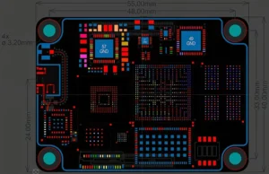
Millimeter-wave (mmWave) PCBs generally refer to circuit boards operating at frequencies in the 24 GHz, 28 GHz, 39 GHz, 60 GHz, 77 GHz, 79 GHz, or even higher bands.
Typical applications include 5G, satellite communications, ADAS vehicle radar, AI high-speed interconnects, aerospace, and high-speed packaging modules.
For PCB manufacturers, millimeter-wave PCBs are no longer simply an “upgraded version of standard high-frequency boards,” but rather represent a comprehensive field that integrates “microwave engineering, precision manufacturing, materials science, and statistical process control.”
What Are the Real Challenges of Millimeter-Wave PCBs?
The fundamental issue with millimeter-wave technology is that the wavelength becomes extremely short;
Any instability of just a few micrometers or even tens of micrometers can result in impedance anomalies, phase shifts, or degraded insertion loss.
For example:
1 GHz: Wavelength approximately 300 mm
30 GHz: Wavelength approximately 10 mm
77 GHz: Wavelength approx. 3.9 mm
Under these conditions, line width errors, copper roughness, resin fiber distribution, lamination misalignment, via placement deviations, surface plating, and glass fiber weaving effects all directly impact RF performance.
Therefore, the core of millimeter-wave PCBs is that “electrical performance consistency” is far more important than mere “electrical continuity”!!
Traditional PCBs only need to ensure electrical continuity, withstand voltage, and be reliable, but millimeter-wave PCBs must control impedance, phase, insertion loss, return loss, group delay, Dk and Df drift, conductor surface effects, and mode conversion.
Typical Design Characteristics of Millimeter-Wave PCBs
Ultra-Low-Loss Materials
Millimeter-wave applications are most sensitive to dielectric loss and conductor loss; therefore, the following two types of materials are typically used:
1. PTFE-based
Examples:
Rogers series: RO3003/RO4350B/RT/Duroid.
These materials feature extremely low Df, stable Dk, and excellent high-frequency performance;
Disadvantages include softness, difficulty in processing, difficulty in drilling, and high thermal expansion.
2. Hydrocarbon Ceramics
Examples: Megtron 6/Tachyon/I-speed. Suitable for high-speed + millimeter-wave hybrid applications
Ultra-Low-Roughness Copper Foil
At millimeter-wave frequencies, current flows only near the surface (Skin Effect).
The skin depth at 30 GHz is only about 0.38 μm.
Therefore, if the copper roughness is 2 μm, it is equivalent to a mountain range, so VLP/HVLP/ULP/RTF ultra-low-roughness copper is used.
Extremely Fine Lines
Millimeter-wave impedance is highly sensitive to line width. Common line widths range from 2 to 4 mils, with gaps of 2 to 3 mils;
At higher frequencies, line widths may even be less than 2 mils.
This places extremely high demands on manufacturing processes regarding etching uniformity, side etching, and line edge roughness.
Highly Sensitive Transmission Line Structures
Common structures include microstrip, stripline, and CPWG (coplanar waveguide), with CPWG being the most common for millimeter-wave applications.
This design offers good EMI performance, stable impedance, easy grounding, and low radiation.
However, manufacturing is challenging because the gap between the trace and ground is highly sensitive; even minor AOI errors can cause deviations.

Extremely Thin Laminate Thickness
Millimeter-wave designs typically use 2-mil, 3-mil, or 4-mil cores to control impedance and achieve the required resistance.
However, manufacturing such thin boards is extremely difficult, as they are prone to wrinkling, warping, and misalignment.
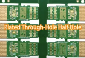
Unique Via Structure
Millimeter-wave vias serve more than just electrical connectivity; they are an integral part of the RF structure.
Backdrilling is commonly used to eliminate via stubs, as these stubs can cause resonance, reflection, insertion loss, and via fences at millimeter-wave frequencies, effectively creating RF shielding.
Additionally, filled vias or VIPPO are typically required to prevent impedance discontinuities and mode transitions.
Special Surface Treatment
Millimeter-wave applications are sensitive to surface roughness and magnetic effects, so ENIG is generally avoided because the Ni layer increases loss.
Common treatments include electroless silver plating, electroless tin plating, ENPIG, ENEPIG (for certain applications), and even bare copper protection.
Challenges in Millimeter-Wave PCB Manufacturing
Extremely Poor Material Processability
Unlike FR4, PTFE is soft and slippery, does not absorb water, is difficult to bond to, and is prone to deformation.
As a result, drilling is extremely difficult. Issues such as smear, rough hole walls, nailhead defects, and resin recession are common.
Extremely Difficult PTFE Via Metallization
PTFE is highly chemically inert. Traditional PTH processes suffer from insufficient adhesion, prone to via bursting, and delamination.
Therefore, plasma treatment is required to increase surface reactivity, which is a critical process for millimeter-wave boards.
Lamination Is Extremely Difficult to Control
Millimeter-wave boards typically involve mixed lamination, using multiple materials with different CTE values.
For example: PTFE + FR4 lamination.
Differences in resin flow, thermal expansion, and expansion/contraction rates lead to issues such as warpage, shift, and delamination.
Extremely High Precision in Circuit Etching
For millimeter-wave applications, it is not just line width that matters, but also edge roughness.
Since high-frequency currents flow along the edges, even if AOI passes, RF performance may still fail.
Controlling Copper Roughness is a Major Challenge
A significant portion of millimeter-wave insertion loss stems from conductor roughness loss.
Therefore, roughening cannot be as aggressive as with FR4, but insufficient roughening leads to lamination delamination, CAF, and inadequate peel strength.
This presents a major trade-off that requires careful balancing.
Impedance Control at the Micron Level
Standard boards allow ±10% tolerance, while high-speed boards allow ±7%.
Millimeter-wave applications often require ±5% or even ±3% tolerance.
Consequently, the manufacturing process must strictly control etching compensation, thermal expansion, Dk variation, copper thickness, and resin flow.
Fiber Weave Effect
Millimeter-wave applications are highly sensitive because the Dk of glass fiber is approximately 6, while that of resin is approximately 2.3.
This leads to localized impedance variations, resulting in phase skew and differential mismatch.
Consequently, millimeter-wave designs employ spread glass, flat glass, or thinner weaves.
Key Points for Millimeter-Wave PCB Production Control
Material Control
Consistency and uniformity of Dk and Df must be controlled for each batch.
Since Dk values may drift between batches, this can directly cause frequency deviations at millimeter-wave frequencies.
Therefore, many manufacturers use fixed lots, fixed suppliers, and fixed resin content for the same project.
Copper Foil Roughness Control
Rz, Ra, and profile must be controlled.
Laminating Parameter SPC
Temperature rise rate, vacuum, pressure curve, gel time, and resin flow must be controlled.
This is because changes in thickness directly affect impedance.
Drill Quality
Millimeter-wave vias are highly sensitive; drill roughness, via misalignment, smear, and surface roughness must be controlled.
Typically, new drill bits, low hit counts, and entry material optimization are employed.
Etching Capability
Edge smoothness is critical—it’s not just about line width; undercut, sidewall profile, and rough edges must be controlled.
Conclusion
In summary, millimeter-wave PCBs represent a highly demanding frontier of electronics manufacturing where performance depends on extreme precision at every level—from materials and copper roughness to via structure and impedance control.
As operating frequencies continue to rise, ensuring electrical consistency, minimizing signal loss, and tightly controlling fabrication processes become critical.
Ultimately, successful mmWave PCB production relies on balancing material limitations and manufacturing capabilities to achieve stable, high-frequency performance.