
We create flexible circuits by printing conductive materials onto a flexible substrate in specific shapes to form circuits with conductive patterns;
They serve as a key component for connecting flexible electronic components.
As a new type of electronic material, flexible circuits hold broad application prospects in various fields, including electronic product manufacturing, biomedicine, and smart wearables.
With the rapid adoption of flexible circuits in the electronics industry, surface-mount technology (SMT) for these circuits is facing significant challenges.
Traditional reflow soldering uses a hot air stream to heat circuit boards and electronic components coated with solder to the solder’s melting point, causing the solder to melt and form a bond.
However, because flexible circuit substrates are not heat-resistant, they are prone to damage during the surface-mount process.
Limitations of Traditional SMT for Flexible Circuits
We widely apply microwave heating in fields such as food processing, petrochemicals, and materials processing because it delivers high efficiency, energy savings, selective heating, and clean, pollution-free operation.
Microwaves offer significant advantages in rapid heating and material processing, but research on the use of microwaves for surface-mount assembly remains limited.
Nowottnick Mathias et al. used microwave treatment on lead-free solder (SnSn3.8Cu0.53min), achieving a maximum temperature of 250 °C, which was sufficient to melt the solder and form good solder joints.
Sato Tadao et al. used a single-mode microwave cavity to achieve the brazing of MgO and Al₂O₃.
Previous studies show that surface currents generate ohmic losses, which rapidly heat metal powders in a microwave magnetic field.
Research Progress of Microwave-Assisted Soldering
This work adopts a single-mode TE102 microwave resonant cavity for heating tests.
Operators complete reliable soldering of zero-ohm resistors on polyimide flexible circuits.
The finished circuits maintain favorable bending resistance.
We test two groups of substrate samples under microwave magnetic fields. One carries solder paste, and the other does not.
Contrasting temperature-rise curves confirm the selective heating effect on solder paste.
Impedance tests evaluate the electrical performance of solder joints.
Zero-ohm resistors on identical circuit substrates form two comparison groups.
One group receives microwave magnetic field treatment, and the other uses conventional heating.
We performed power-on testing of LEDs mounted under a microwave magnetic field to verify whether microwave treatment damaged the surface-mount components.
Researchers observe cross-sections of solder joints with scanning electron microscopy (SEM).
They compare microstructures from two heating routes. One group receives microwave magnetic field treatment.
The other group uses conventional heating.
Solder joints under rapid microwave treatment form thinner IMC layers.
The abbreviation IMC stands for intermetallic compound. Thinner intermetallic layers benefit the mechanical strength of solder joints.
An Introduction to the Theory of Microwave Single-Mode Resonant Heating
We can calculate the energy dissipation of electromagnetic waves in bulk materials using Equation (1):

In the equation,
- Pluv is the microwave power absorbed per unit volume, ω is the microwave frequency;
- ε₀ and μ₀ are the permittivity and magnetic permeability of air, respectively;
- ε″ and μ″ are the imaginary parts of the relative permittivity and relative magnetic permeability of the material, respectively;
- →E is the electric field strength;
- and →H is the magnetic field strength.
Microwave Energy Loss in Bulk Materials
Metal powder particles interact strongly with microwave magnetic fields.
They absorb microwave energy efficiently, as reported in prior literature.
Particle size and electrical conductivity are key influencing factors. These properties change the microwave power dissipation inside the particles.
It is difficult to directly calculate or analyze the loss characteristics of microwaves in powdered materials using Equation (1).
We can calculate the dissipated power of microwaves in powdered materials (especially metal powders) using Equation (2):

In the equation,
- αc is the attenuation constant of the metal particles;
- μc is the magnetic permeability of the metal powder;
- σc is the electrical conductivity of the metal powder;
- ρs is the porosity of the sample;
- rp is the average particle size of the powder;
- rc is the radius of the metal powder; and ε″d is the imaginary part of the dielectric constant of materials such as flux.
Power Dissipation Model for Powdered Metal Composites
This experiment uses AG30 solder paste from Anlixin Company. The paste is used for surface-mount assembly on flexible circuits.
It is a composite made of Sn96.5Ag3Cu0.5 alloy powder and organic binder.
The first term in Equation (2) describes microwave power absorption.
Metal powder inside the solder paste relies on surface currents for energy dissipation under microwave magnetic fields.
Particle size, conductivity, and porosity determine this dissipated power.
The second term in Equation (2) covers organic components.
Organic materials absorb microwave energy via dielectric loss induced by microwave electric fields.
Organic fraction and equivalent dielectric constant dominate this loss.
The first term contributes much more energy loss for metal-rich composites. Its value greatly exceeds the loss from the second term.
Metal powders and metal-filled composites heat readily in the core of microwave magnetic fields.
We therefore carry out rapid surface-mount soldering tests inside a TE102 single-mode microwave resonant cavity.
Resonance Principle of the TE102 Microwave Cavity
The relationship between the resonant frequency and the cavity dimensions in a rectangular resonant cavity is as follows:

Rectangular resonators have three characteristic dimensions. They include the broad side a, narrow side b, and length l.
We define resonance modes by integers m, n, and p. Each mode delivers unique resonance frequencies and wavelengths.
It also creates a distinct electromagnetic field distribution.
Equation (3) supplies the theoretical basis for dimension selection. This experiment adopts a TE102 single-mode resonator.
Its working frequency is 2.45 GHz. Its geometric size is 86.4 mm × 43.2 mm × 173.6 mm.
Experimental System
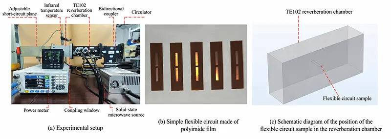
The single-mode microwave cavity processing system used in this paper is shown in Figure 1(a).
A solid-state microwave source generates microwaves at a frequency of 2.45 GHz, and the heating cavity is a TE102 resonator;
We connect a bidirectional coupler to a microwave power meter to measure the incident and reflected powers in real time;
An infrared thermometer monitors the temperature of the solder joint during the soldering process through the observation window above the resonant cavity.
The experimental specimen is a flexible polyimide substrate (30 mm × 8 mm × 0.8 mm) with two copper strips plated on its front side (each strip measuring 1.5 mm × 8.5 mm, spaced 1 mm apart), as shown in Figure 1(b).
We printed solder paste (Sn96.5Ag3Cu0.5) onto the flexible polyimide circuit board using a steel stencil.
Operators take surface-mount parts, including 1206 chip resistors. They place these components lightly onto the solder paste.
The assembled samples move to the center of the resonant cavity. Figure 1(c) illustrates this placement.
Researchers perform microwave heating experiments under this setup.
Numerical simulation results show the electric field strength inside the cavity containing the flexible circuit board, as shown in Figure 2.
When we placed the sample at the center of the TE102 cavity, we found very low microwave electric field strength but maximum microwave magnetic field strength at the sample’s location.

Results and Discussion
Sample Heating Conditions
First, we compared the temperature rise of flexible circuits with and without solder paste when exposed to the microwave magnetic field at its center.
In the experiment, we placed flexible circuit samples with and without solder paste at the center of a TE102 single-mode microwave resonator, respectively.
The power of the solid-state source was set to 230 W, and the heating time was 10 s.
A microwave power meter was used to measure the incident and reflected power; the results are shown in Table 1.
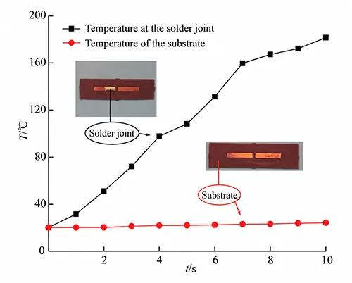
An infrared thermometer was used to measure and record the temperatures of the solder joints and the substrate in real time during the soldering process; the experimental results are shown in Figure 3.
The solder paste on the solder joint rapidly heated to 181.6°C within 10 s, whereas the substrate without solder paste showed almost no temperature rise under the same microwave heating conditions.
Microwave fields produce selective heating effects. Solder paste temperature climbs at an extremely fast rate.
The polyimide flexible substrate receives barely any heat. This heating feature protects the substrate’s favorable performance.
Its original excellent properties remain intact.
| Incident Power (W) | Reflected Power (W) | Dissipated Power (W) |
|---|---|---|
| 227 | 52.5 | 174.5 |
| 226 | 51.6 | 174.4 |
| 231 | 52.1 | 178.9 |
| 227 | 53.1 | 173.9 |
| 228 | 52.7 | 175.3 |
Table 1. Internal Power Dissipation of the Cavity
Rapid Surface Mount Assembly Using Microwave Technology
Building on the temperature tests, we further analyzed the impedance of the solder joints treated with microwave technology.
First, we screen-printed solder paste onto a polyimide flexible circuit board.
Next, we placed a 1206 zero-ohm surface-mount resistor on the solder paste and positioned it at the center of the TE102 resonant cavity.
The microwave source power was set to 230 W, and the heating time was 10 s.
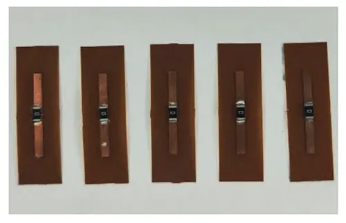
After soldering, as shown in Figure 4, we measured the resistance of the solder joints and the zero-ohm resistor using an ohmmeter.
To minimize experimental and measurement errors, we conducted multiple sets of experiments; the measurement results are shown in Table 2.
| Resistance (mΩ) | Average Value (mΩ) |
|---|---|
| 27.7 | |
| 27.6 | |
| 27.4 | 27.56 |
| 27.4 | |
| 27.7 |
Table 2. Measurement Results of Resistance in Five Experimental Groups
The measured average resistance of the whole assembly reaches 27.56 mΩ.
This structure covers the zero-ohm resistor, two solder joints, and copper traces on both substrate segments.
The value is far below the benchmark from conventional thermal soldering. Andersson Henrik A and his team recorded 1.5 ± 0.3 Ω in their research.
Microwave magnetic field rapid assembly produces flexible circuits with smaller joint resistance.
This outcome outperforms earlier published data. Lower solder-joint resistance improves the electrical performance of flexible circuits.
Electrical Resistance of Microwave-Soldered Solder Joints
Additional tests evaluate bending performance and mechanical reliability.
We manufacture these specimens by microwave magnetic field surface mounting.
Figure 5 records the related test results. We perform bending tests on the flexible circuit samples, and the circuits keep good electrical conductivity.
To minimize experimental and measurement errors, we carry out bending resistance measurements on multiple sets of flexible circuit samples; we present the results in Table 3.
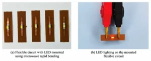
At the same time, we used microwave-assisted rapid mounting to attach 0806 surface-mount LEDs to the polyimide flexible circuit.
After connecting the flexible circuit to a power source at both ends, the surface-mount LEDs lit up normally, as shown in Figure 6.
Using microwave selective heating to rapidly mount components onto the flexible circuit does not damage the components.

| Resistance (mΩ) | Average Value (mΩ) |
|---|---|
| 27.8 | |
| 27.6 | |
| 27.4 | 27.66 |
| 27.5 | |
| 28.0 |
Table 3. Resistance Measurement Results of the Flexible Circuit Sample
SEM Analysis of Sample Cross-Sections
This paper continues the measurement and analysis of the microstructure of solder joints.
To observe the microstructure inside the solder joints, a wire was cut to cut the solder joint in half from the center; after polishing, SEM imaging was used to analyze the microstructure of the sample.
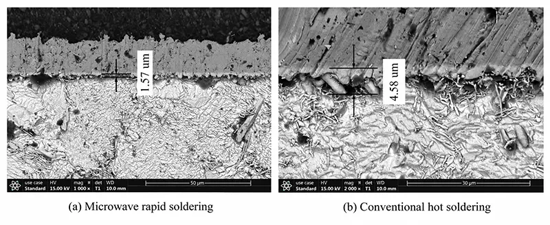
As shown in Figure 7, due to the difference in metallic materials between the solder joint and the copper pad, a scallop-shaped IMC layer formed between the solder joint and the copper pad.
The IMC layer is relatively brittle and has a significantly different coefficient of thermal expansion from the substrate;
If the IMC layer grows too thick, it is prone to fracture, whereas a thinner IMC layer helps improve the mechanical properties of the solder joint.
Samples stay inside the TE102 microwave resonant cavity for 10 seconds. The IMC layer at the solder joint grows to roughly 1.57 μm.
Conventional heating forms a much thicker intermetallic layer. The measured IMC thickness on these cross-sections reaches about 4.58 μm.
The increase in the IMC layer thickness under the conventional method is primarily due to the longer heating time.
Microstructural analysis indicates that, compared to conventional processing methods, joints produced by microwave rapid welding exhibit superior mechanical properties.
Conclusion
This work verifies the selective heating effect of microwave magnetic fields on solder paste.
The effect supports fast soldering for temperature-sensitive surface-mount devices on flexible circuits.
A TE102 single-mode microwave resonator serves as the heating platform.
Researchers solder surface-mount resistors and LEDs onto polyimide flexible substrates.
The finished flexible substrates maintain excellent bending performance after soldering.
Resistance tests target zero-ohm resistors joined by microwave magnetic field soldering.
Measured solder joint resistance stays at a low level. This feature helps upgrade the electrical performance of flexible circuits.
The LEDs placed via microwave rapid placement were still able to light up normally, indicating that the microwave magnetic field did not damage them.
Researchers compare solder joint microstructures from two processes. One uses microwave rapid mounting. The other relies on conventional heating.
SEM observations confirm the difference. Microwave-treated solder joints form thinner IMC layers. Thinner intermetallic layers strengthen solder joints.
This study puts forward a microwave rapid surface-mount technique. It offers a feasible route for high-volume fast assembly on flexible circuits.
The technology accelerates flexible circuit development and industrial application.